RC Column Design
Whether a column is adequate is not settled by a single check. The strength of the section under axial load and bending is one question, its shear and torsion strength is a second, and whether the reinforcement satisfies the code's detailing rules is a third — often the governing one. Once the seismic code applies, confinement zones form at the ends of the column, and inside them the stirrup spacing and confinement reinforcement follow different rules.
Creating the calculation
Pick RC Column Design in the Calculation Gallery and add it to your project with "Start Calculation". The screen splits in two: the input panel on the left, four tabs on the right — Design, Detailed Design, Interaction Diagrams and Section State.
The input panel has seven sections. The load combinations are not among them: you define those in the table at the top right of the Design tab.
| Section | Data you define |
|---|---|
| Specification | Design code and seismic code |
| Section Geometry | Section type, dimensions and cover |
| Reinforcement Layout | The longitudinal bars used in check mode |
| Stirrup Layout | The stirrups of the support and mid-span zones |
| Materials | Concrete and reinforcing steel grade |
| Design Options | The diameters auto design may try, and the slenderness inputs |
| Seismic Design | Ductility class and confinement zone length |
Specification
The design code applied is TS 500. You can leave the seismic code as None or select TBDY 2018.
Select TBDY 2018 and the confinement zone rules at the column ends, the confinement reinforcement calculation and the capacity shear all come into play. They apply together — there is no separate switch to turn any of them on or off.
Section geometry
You can work with rectangular, circular and hollow circular sections. A rectangular section takes the width, the height and the top, bottom and side cover. Circular sections need the diameter and the cover.
Once you pick the section type, the reinforcement and stirrup layouts follow it. On a circular or hollow circular section the bars have to be circumferential and the stirrup has to be circular or a spiral.
Reinforcement layout
The values in this section are used when you run Check Reinforcement. When you run auto design, the engine writes the reinforcement it selected back into these fields, so the practical route to adjusting a design is to run auto design first.
On a rectangular section the layout is symmetric. There are always four corner bars, and you give the diameter and count of the intermediate bars in X and Y separately. Intermediate counts must be even, because they are split equally between opposite faces.
On a circular or hollow circular section you give a single diameter and count, and the bars sit at equal angles around the perimeter.
⚠️ The face-by-face layout, with different top and bottom reinforcement, cannot be used in this macro. The seismic code's column detailing rules are written for a symmetric arrangement, so the engine rejects such a layout. To study a section like that, use the Section Analysis macro.
Stirrup layout
You define the stirrup separately for two zones.
| Zone | Where it is |
|---|---|
| Support Zone | The confinement zone at the ends of the column, where the spacing limit and the confinement reinforcement are tighter |
| Mid-span Zone | The middle region between the two confinement zones |
Both zones take a diameter and a spacing. On a rectangular section you select the stirrup type as single, double, triple or diamond and give the leg counts in X and Y. On circular sections you use a circular stirrup or a spiral, and a spiral also takes the pitch.
Materials
You select the concrete and reinforcing steel grade. Because this macro produces a code check, the concrete side uses the code's equivalent rectangular compression block and the steel side the elastoplastic diagram without strain hardening. The material factors are applied with TS 500's own values, and — you do not enter them here.
If you want the section's real behaviour instead, the effect of confinement or the moment-curvature curve, you can take the same section into the Section Analysis macro, where you choose the constitutive model and the factors yourself.
Design options
This section decides which diameters auto design may try. The longitudinal reinforcement candidates and the stirrup candidates are separate lists, and the engine looks through them for the smallest reinforcement that satisfies every load combination.
For the slenderness screening you give the column's clear height and the effective length factor. The factor comes with two ready choices: 1.0 for a braced, laterally restrained column and 2.0 for a cantilever with a free end.
⚠️ Leave the clear height blank and no slenderness screening is done. Enter a value and the engine compares against the code limit and reports a column that exceeds it. No moment magnification or second-order analysis is performed, so for those columns you have to carry out that calculation separately.
Seismic design
This section matters once a seismic code is selected. You choose the ductility class as high ductility (YSD) or limited ductility (SSD). Your choice sets the bar-diameter multiplier in the stirrup spacing limit and some of the minimum requirements.
Leave the confinement zone length blank and the code formula is used; enter your own value and the calculation uses it. For the capacity shear and confinement zone checks to run, you also need to give the column's clear height.
Load combinations
You define the combinations in the table on the Design tab. "Add" opens a row, and on each row you give the combination's name, its type (ULS or SLS) and its category (Gravity, Wind, Seismic, Other).
Each row takes six components.
| Component | What it is |
|---|---|
| N (kN) | Axial force, compression positive |
| M1 (kNm) | Bending moment about the local 1 axis |
| M2 (kNm) | Bending moment about the local 2 axis |
| V1 (kN) | Shear force along the local 1 direction |
| V2 (kN) | Shear force along the local 2 direction |
| T (kNm) | Torsional moment |
⚠️ The values you enter must already be factored for ultimate strength. The calculation applies no load factors of its own. Gravity load factors, and the increases the code requires in seismic combinations (the equivalent-static to modal-combination increase, the overstrength factor and the like), are applied by you and entered as the result.
Auto design and check
Two buttons sit under the section drawing on the Design tab.
| Button | What it does |
|---|---|
| Auto Design | Searches the candidate lists for the smallest reinforcement and stirrup that satisfy every combination |
| Check Reinforcement | Runs every check on the reinforcement and stirrup layout you defined in the left panel |
When auto design finishes, the longitudinal reinforcement it found and the stirrups of both zones are written into the fields in the left panel. So when the result is not what you want, you can change a diameter or a spacing and test your own arrangement with Check Reinforcement.
The line under the buttons tells you which mode ran and how it went: Reinforcement Auto-Designed or Reinforcement Checked, next to an All Checks Passed, Warnings Present, Design Failed or Check Failed badge.
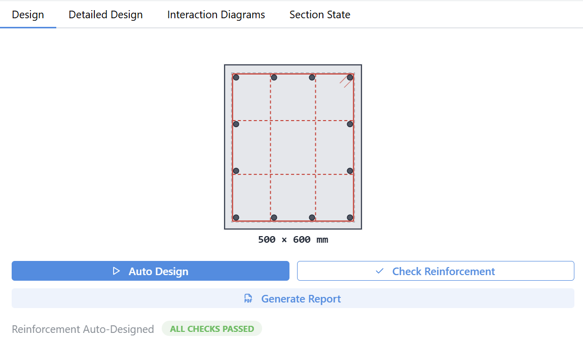
If no diameter in the candidate list can carry the demand, the result is reported as infeasible, and whether that comes from the axial load, the reinforcement ratio, shear, torsion or the detailing rules is stated as well.
Reading the design results
The results appear on the same tab, below the buttons. The longitudinal reinforcement card gives the total steel area, the reinforcement ratio and how the bars are split between the corner and intermediate groups. The stirrup card gives the diameter and spacing of the confinement zone and the mid zone separately.
The flexural combinations table lists each combination's axial force, its two moments, its demand/capacity ratio and its outcome. A ratio below 1 marks the combination as Pass and a ratio above it as Fail.
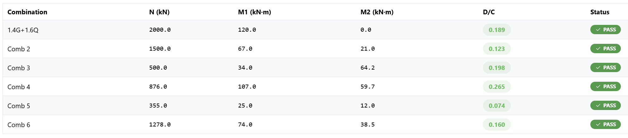
Shear and torsion results have cards of their own. Shear is reported for the two directions separately, and within each direction for the confinement and mid zones separately. The torsion card shows which action governs and the combined shear-plus-torsion ratio.
Detailed Design
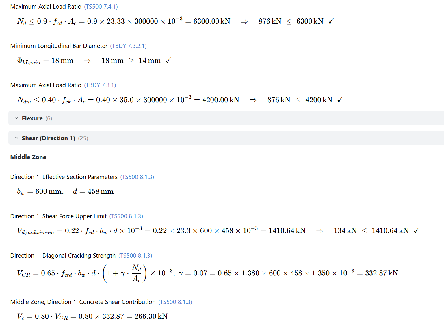
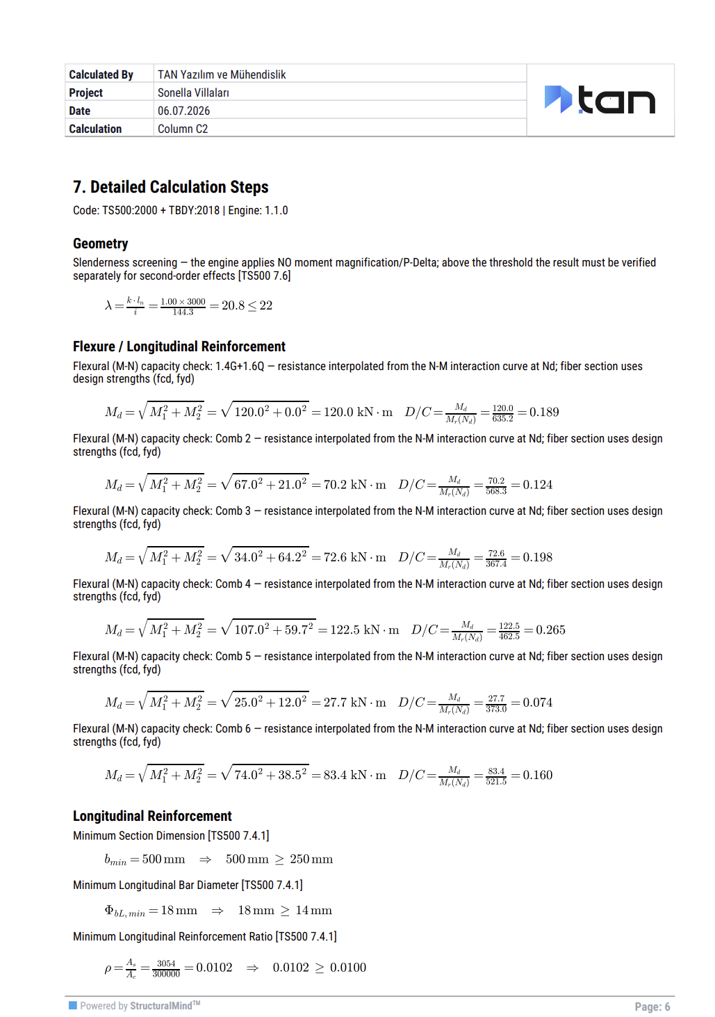
The Detailed Design tab carries the calculation step by step. The steps are grouped under geometry, material, flexure, shear in the two directions, torsion, longitudinal reinforcement, detailing rules and the N-M surface.
Each step shows the number of the code clause applied, the formula used, the numbers substituted into it and the outcome of the comparison. When a step fails, the tab label is marked too, so you do not have to hunt for the rule that failed.
Reading the interaction diagrams
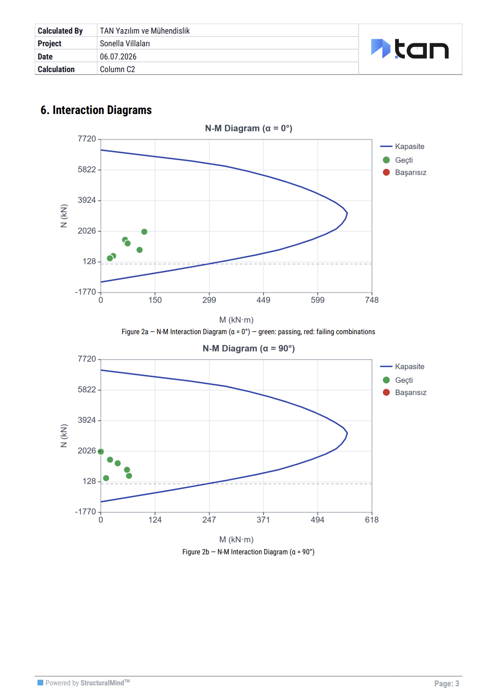
This tab shows the section's strength envelope together with where your load combinations fall inside it. The four cards at the top give pure compression, pure tension, the balance axial load and the maximum moment.
The N-M diagram carries the 0° and 90° curves, and your combinations land on them as points. Passing combinations are green and failing ones red, so you can see how close a combination sits to the limit without reading the numbers.
In the Mx-My diagram you can select an axial level, or pick one of your combinations with "Select combination". Pick a combination and the contour is interpolated to that combination's axial load, so the point and the contour are compared at the same axial level.
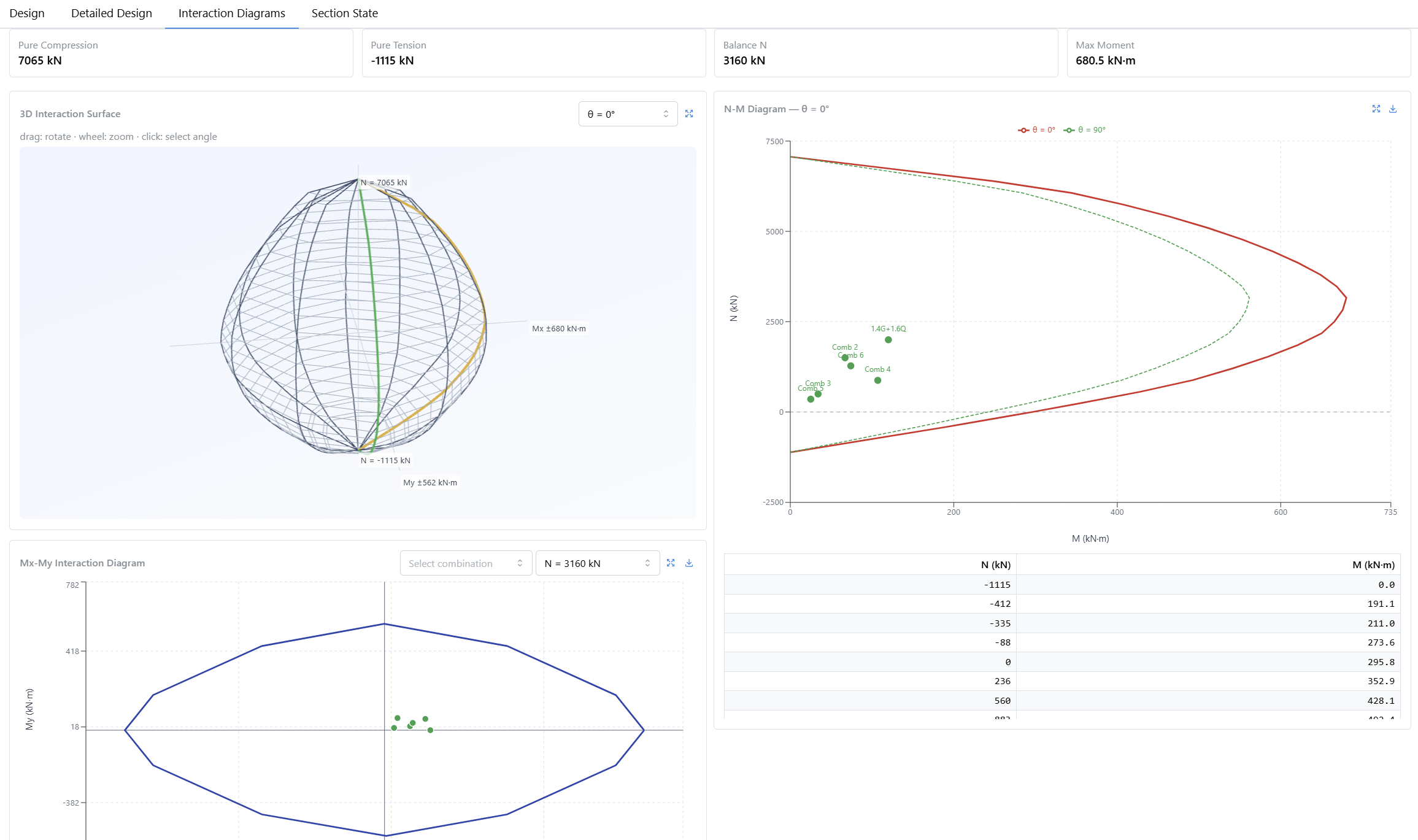
You can drag the three-dimensional surface to rotate it, zoom with the wheel, and click it to pick the angle the N-M diagram is drawn at.
Section state
On the Section State tab you select a combination and see the section's fiber stress distribution under it. The governing combination is marked in the table.
Beside the figure you get the neutral axis depth and angle, whether the solution converged, that combination's axial force and moment demands, and the section's moment capacities at the same point.
The fiber stress state is not written to the saved calculation — it is produced when you need it. Start it with "Compute fiber state". If your results are out of date the state cannot be computed and you have to recalculate first.
Generating the report
Generate Report on the Design tab produces the PDF. It has eight sections.
| Section | Contents |
|---|---|
| 1. Section and Reinforcement | Geometry, longitudinal bars and the stirrups of both zones |
| 2. Section Drawing | The section with its bars and stirrups |
| 3. Design and Material Information | Design code, seismic code, material grades and factors |
| 4. Load Combinations | The list of combinations you entered |
| 5. Design Summary | Reinforcement, stirrups and the demand/capacity ratio per combination |
| 6. Interaction Diagrams | The 0° and 90° diagrams with the combinations in pass and fail colours |
| 7. Detailed Calculation Steps | The step-by-step trail with clause numbers and formulas |
| 8. Material Stress-Strain Curves | The material curves used in the calculation |
The report follows the language of the interface: run a calculation in the English UI and the report comes out in English.
Whether the results are current
The state of your result is shown under the input panel.
| State | What it means |
|---|---|
| Analyzed | The saved result is current. The engine version and the time of the run are shown with it |
| Inputs changed | You changed an input after the calculation, so the results no longer belong to the column on screen |
| Older engine version | The result was produced with an earlier version of the calculation engine |
Producing a report and computing the fiber state both require a current result. In the other two states, refresh the calculation with Auto Design or Check Reinforcement first.
When you want to study the section's behaviour
This macro answers the questions the code asks and returns a Pass or Fail for every rule. When you want the section's expected behaviour instead — the moment-curvature curve, the ductility ratio or the effect of confinement — you can take the same section into the Section Analysis macro. Its step-by-step use is on the How to Use Section Analysis page.
Which rules the calculation applies, which assumptions it makes and what it leaves out are covered on the Column Design and Column Design — Verification pages.